 Evu Cleanup Edit Several ( Drawing Editor )
Tool summary :
- To clean up erection views:
- When you are done:
Also see :
|
- Drawing Editor (where Erection View Cleanup is a tool)
- Erection view (drawing type affected by Erection View Cleanup Several )
- Relocate member labels to default locations (undoes relocations made here, in cleanup)
- Piecemarks (may be affected using Erection View Cleanup Several )
- Section sizes (may be affected using Erection View Cleanup Several )
- Camber annotations (may be affected using Erection View Cleanup Several )
- Elevation offsets (may be affected using Erection View Cleanup Several )
- Evu Cleanup Edit by Location (alternative)
- Erection View Cleanup by Piecemark (alternative)
- Erection View Cleanup by Member Number (alternative)
- Ctrl-drag (to rotate a piecemark or etc. to rotate around its origin)
- From erection views to erection sheets (topic)
- Tip1: To save time in Erection View Cleanup , employ options for hiding/showing " Cross-section marks " and for " Check overwriting pcmks and sizes " when you Detail Erection Views.
- Tip 2: To move marks on an erection view, you can drag them in Select Items mode instead of using " Relocate ." To rotate them, you can Ctrl -drag .
page 1 | contents | tools > erection view cleanup > | tools | top
Step-by-step instructions for Erection View Cleanup Several :
Before starting: You can optionally select members, then adjust your selection in step 2.
1 . While the erection view you want to change is your current drawing, invoke Erection View Cleanup Several using one of the following methods:
Method 1 : Click the Erection View Cleanup Several icon. The icon can be taken from the group named ' Tools ' and placed on a toolbar (classic) or the ribbon (lightning).
Method 2 : If " Drawing Editor layout style " is ' Classic ', you can use the menu system to choose Tools > Erection View Cleanup > Edit Serveral .
Method 3, 4 or 5 : Erection View Cleanup Several can also be invoked using a keyboard shortcut , the context menu , or a mode . For the ' Lightning ' layout style, configuration of the interface is done using Customize Interface .
Method 6 : With Erection View Cleanup Mode mouse bindings active, right-click ( Several ).
2 . The Erection View Cleanup window opens. Select - Pan - Menu mouse bindings become active. The status line tells you the total number of members in the drawing and the number of those members that are hidden. Note that you can do step 2a after 2b as well as before 2b.
|
|
|
mouse bindings |
2a : Select one or more members whose marks or member lines you want changed. For example, you can draw an area box to select the member(s).
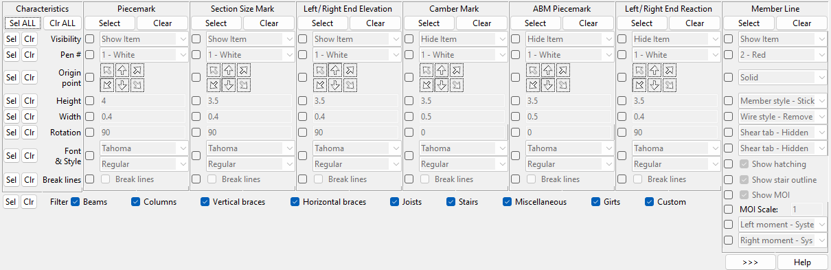
2b : Designate on this window the changes you want to apply to the selected members. Use the options under the " Member Types Affected " heading and under the " Characteristics " column to designate the changes you want to make to marks or member lines. Under the " Member Types Affected " heading, select the types of members you want the changes you designate applied to.
2c : Press the Enter key or right-click ( Menu ) and choose " Return " on the context menu to signal to Erection View Cleanup Several that you are done selecting members.
Tip: The boxes that are checked under the " Member Types Affected " heading directly affect the types of members that you can select in this step.
3 . The changes you designated in step 2b are applied to the members you selected in step 2a. If you later redail the erection view, your changes to the members will be retained.
Alternative 1 : Repeat steps 2a through 2c to make additional changes to members.
Alternative 2 : Close the Erection View Cleanup window and end the Erection View Cleanup Several operation using any one of the following methods. Method 1: Press the Esc key. Method 2: Right-click ( Menu ) and choose Cancel on the menu . Method 3: Click the "X" button (
) in the upper, right corner of the window.
Note: Changes made to an erection view using this option do not become permanent until you Save those changes. Until you Save your changes, you can Revert to the previously saved version of your drawing.
page 1 | contents | tools > erection view cleanup > | tools | top
| Member Types Affected |
Beams and/or Columns and/or Vertical braces and/or Horizontal braces and/or Joists and/or Stairs and/or Miscellaneous and/or Girt and/or Custom .
When a member type is checked (
), selections made under columns on the Erection View Cleanup window (this window) are applied to that member type when you select members and press the Enter key (see step 2 ).
When a member type is not checked (
), members of that type are not affected by cleanup operations you perform while this window is open.
Tip: Set these options first. They are found at the bottom of the Erection View Cleanup window.
Note: " Misc " selects both miscellaneous members and legacy miscellaneous members .
page 1 | contents | tools > erection view cleanup > | tools | top
Characteristics: See below .
Piecemark: Options under this column let you change the " Visibility ," " Pen number ," " Relocate ," " Origin ," " Height ," " Width " or " Rotation " of member piecemarks .
|
Section Size Mark: Options under this column let you change the " Visibility ," " Pen number ," " Relocate ," " Origin ," " Height ," " Width " or " Rotation " of member section sizes .
|
Left End Elevation: Options under this column let you change the " Visibility ," " Pen number ," " Relocate ," " Origin ," " Height ," " Width " or " Rotation " of left end elevation offset marks.
|
Note: When the elevation offset mark is in the middle of the beam, options under the " Left End Elevation " let you change that mark.
Right End Elevation: Options under this column let you change the " Visibility ," " Pen number ," " Relocate ," " Origin ," " Height ," " Width " or " Rotation " of right end elevation offset marks.
|
Note: " Right End Elevation " options cannot be used to alter an elevation offset mark that has been placed in the middle of the beam.
Camber Mark: Options under this column let you change the " Visibility ," " Pen number ," " Relocate ," " Origin ," " Height ," " Width " or " Rotation " of beam camber annotations .
|
ABM Page-Line: Options under this column let you change the " Visibility ," " Pen number ," " Relocate ," " Origin ," " Height ," " Width " or " Rotation " of the ABM page-line (or system ID) of the selected member's main material.
|
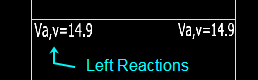
Left End Reaction: Options under this column let you change the " Visibility ," " Pen number ," " Relocate ," " Origin ," " Height ," " Width " or " Rotation " of left end reactions.
|
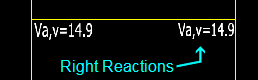
Right End Reaction: Options under this column let you change the " Visibility ," " Pen number ," " Relocate ," " Origin ," " Height ," " Width " or " Rotation " of right end reactions.
|
Member Line: Options under this column let you change the " Visibility ," or " Pen number " or " MOI " of member lines.
|
page 1 | contents | tools > erection view cleanup > | tools | top
| Characteristics (rows on this window) |
Visibility: Hide or Show or Toggle . Tip: You can hide braces during Detail Erection Views .
|
Select ' Hide ' if you want marks or member lines of the selected members whose " Type " is checked to disappear in the erection view that is your current drawing.
Select ' Show ' if you want the selected marks or member lines to be shown.
Select ' Toggle ' if you want the selected marks or member lines to be shown if they are currently hidden, but to be hidden if they are currently shown.
Pen number: 1 or 2 or 3 or 4 or 5 or 6 or 7 . This option only works for member lines when the " Steel member style " is ' Stick ' or ' Stick + wire '.
|
Select the ' pen number for plotting ' (on-screen display color) that corresponds to the pen that you want your printer to use to draw marks or member lines . The marks or member lines for members that you select whose " Type " is checked are redrawn on-screen in this color.
For a TrueType " Font ," this option affects the display color of that font while you are in the Drawing Editor , but does not, in any way, affect the plotted appearance of the font.
For the ' SDS2 ' " Font ," the pen color sets the stroke weight (thickness) of characters. Line Weights assigns a particular thickness to each " Pen color ."
For non-text items such as member lines: Line Weights assigns a particular thickness to each " Pen color ."
Relocate: ![]() or
or ![]() . This option has been removed because now it is easier to relocate erection view labels just by clicking and dragging them. See the video below.
. This option has been removed because now it is easier to relocate erection view labels just by clicking and dragging them. See the video below.
|
Origin: Top left or Top center or Top right or Bottom left or Bottom center or Bottom right origin. The selected button is highlighted green and chooses an origin point for the label as shown below:
| • = origin | ||
|
|
|
|
|
|
|
|
Each selected mark type for members that you select whose " Type " is checked is placed as specified with respect to its origin point.
' Top left ' places the mark so that its origin point is at the top, left of the text.
' Top center ' places the mark so that its origin point is at the top, center of the text.
' Top right ' places the mark so that its origin point is at the top, right of the text.
' Bottom left ' places the mark so that its origin point is at the bottom, left of the text.
' Bottom center ' places the mark so that its origin point is at the bottom, center of the text.
' Bottom right ' places the mark so that the origin point is at the bottom, right of the text.
Height: The height in millimeters of the letters/numbers of each selected mark type for members that you select whose " Type " is checked ( ![]() ).
).
|
Font dependencies: This applies to whatever font is selected as the " Font & Style ," regardless of whether that font is a TrueType font or the ' SDS2 ' font.
Default: The default " Sizes " for piecemarks and section sizes in erection views is set in Home > Project Settings > Fabricator > Drawing Presentation .
Width: The width/height ratio of the letters/numbers of each selected mark type for members that you select whose " Type " is checked ( ![]() ).
).
|
Font dependencies: This applies to whatever font is selected as the " Font & Style ," regardless of whether that font is a TrueType font or the ' SDS2 ' font. For a TrueType font, a ratio of ' 0.6 ' renders that font at its native width. A ratio larger than ' 0.6 ' stretches the font. A ratio less than ' 0.6 ' compacts the font. For the ' SDS2 ' font, ' 0.4 ' is the default choice.
Default: The default " Sizes " for piecemarks and section sizes come from Home > Project Settings > Fabricator > Drawing Presentation .
Rotation: A positive or negative (-) number of degrees ( 360 to -360 ). This rotation is applied to each selected mark type for members that you select whose " Type " is checked ( ![]() ).
).
|
Tip: You can Ctrl -drag an erection view member label to rotate it around its origin. Ctrl + Shift -drag rotates it at 45 degree increments.
Font & Style: Any font that is listed can be selected for the selected mark type for members that you select whose " Type " is checked ( ![]() ). Any style (such as ' Bold ' or ' Bold Italic ' or ' Italic ' or ' Regular ') that is available for that font can be applied to that font.
). Any style (such as ' Bold ' or ' Bold Italic ' or ' Italic ' or ' Regular ') that is available for that font can be applied to that font.
|
For a TrueType font , such as any of those shown here, set the " Width " to ' 0.6 ' to have the font rendered at its native width. |
Related settings on this window: The " Height " sets the font size. If you select the ' SDS2 ' font, be aware that the " Pen number " affects the thickness of the font when it is plotted.
Also see: " Member labels font " and " Member font style " (at Home > Project Settings > Fabricator > rawing Cosmetics > the " Fonts " tab > ) determine the font and font style that are applied automatically during Detail Erection Views .
|
If this box is checked (
If the box is not checked (
page 1 | contents | tools > erection view cleanup > | tools | top
| Special Member Line Options |
Line type: Solid or Dotted or Dashed or Long-dashed or Dash dot dash or L-dash dash or L-dash dash dash .
|
|
Select the line type that you want to be applied to the member lines of selected members whose " Type " is checked.
Member style: Stick or Wire or Solid .
|
Select the member style that you want to be applied to the selected members whose " Type " is checked.
' Stick ' draws members with a single line along the workline of the member(s).
' Wire ' draws the materials that make up the member(s) with lines showing their true structural shape.
' Solid ' draws the materials that make up the member(s) in proportion to their true structural shape and also shades them per their " Surface finish ."
Wire-style hidden lines: Removed or Dashed or Solid . This applies to selected members whose " Member Style " is ' Wire '.
|
Select the line type style that you want to be applied to hidden lines of the selected members whose " Type " is checked.
' Removed ' hides lines that are covered by other steel in a view.
' Dashed ' causes hidden lines to appear as dashed lines.
' Solid ' causes the lines that are covered by other steel to appear as solid lines.
Left end shear tab symbol: System or Hidden or Near side or Far side . This applies to the left ends of selected beams whose member lines are visible in drawings of plan views, and only when Process > " Show shear tab location on erection views " was checked ( ![]() ) when such a view was created.
) when such a view was created.
|
Select the indicator, if any, that you want to be applied to member lines of the selected members whose " Type " is checked.
' System ' applies the shear plate side indicators on the left end of the beam on the side of the beam web if, and only if, in Modeling , the member has a single-plate ' Shear ' connection on that side.
' Hidden ' hides the shear plate side indicator on beam's left end, even if, in Modeling , that beam has a single-plate ' Shear ' connection on one side of the web.
' Near side ' applies the shear plate side indicator on the left end of the beam indicating the near side of its web, even if, in Modeling , it lacks a single-plate ' Shear ' connection on that side.
' Far side ' applies the shear plate side indicator on the left end of the beam indicating the far side of its web, even if, in Modeling , it lacks a single-plate ' Shear ' connection on that side.
Also see: Show shear tab location on erection views ( Detail Erection Views window) sets whether the shear plate side indicator is shown on erection plans.
Right end shear tab symbol: System or Hidden or Near side or Far side . Same as " Left end shear tab symbol ," except that this applies to the right end of the member.
If this box is checked (
If the box is not checked (
| YouTube video: Stair Member Line .
|
If this box is checked (
If the box is not checked (
Show MOI: ![]() or
or ![]() . MOI stands for member orientation indicator.
. MOI stands for member orientation indicator.
|
If this box is checked (
If the box is not checked (
Tip: To move an MOI, you can drag it in Select Items mode.
MOI scale: ![]() or
or ![]() . The value you enter here will be applied even if you auto detail this erection view again.
. The value you enter here will be applied even if you auto detail this erection view again.
|
If this box is checked (
If the box is not checked (
Left end moment symbol: System or Hidden or Shown. This applies when the " Steel member style " is ' Stick ' or ' Stick + wire ' and the member is a beam.
| YouTube video:Left [or Right] end moment symbol .
|
|
' System ' automatically displays a moment symbol on the left end of the beam if and only only if, in Modeling , the member has a ' Bolted ' or ' Welded ' " Moment type " connection on that end.
' Hidden ' will hide the moment symbol on beam's left end, even if, in Modeling , that beam has a ' Bolted ' or ' Welded ' " Moment type " connection on the left end.
' Shown ' displays a moment symbol on the left end of the member even if, in Modeling , the beam lacks a ' Bolted ' or ' Welded ' " Moment type " connection on that end.
Right end moment symbol : System or Hidden or Shown . Same as " Left end moment symbol ," except that this applies to the right end of the member.
|
page 1 | contents | tools > erection view cleanup > | tools | top
![]() To close this window :
To close this window :
Use any one of the following methods to close this window (see step 3 ):
Method 1 : Press the Esc key.
Method 2 : or right-click ( Menu ) and choose " Cancel " on the menu .
Method 3 : Click the "X" button (
page 1 | contents | tools > erection view cleanup > | tools | top